What are the Functions of Solid State Relay?
Solid state relay is a contactless switch composed of microelectronic circuit, discrete electronic device and power electronic power device. The isolation device is used to realize the isolation of the control terminal and the load terminal.
The input end of solid state relay uses small control signal to directly drive large current load. In addition to understanding what a solid state relay is, we also need to know its function. In the following, atorelays.com will give you a detailed introduction.
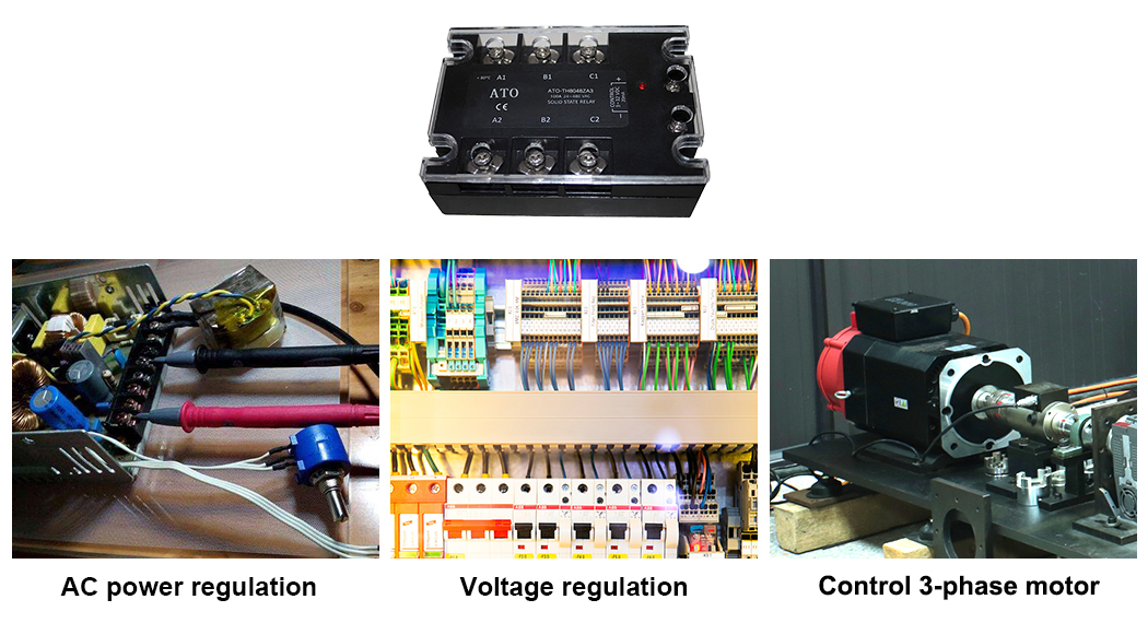
- AC power regulation.AC power regulation is a commonly used method for Z-type SSR solid state relay, and it can also realize PID regulation. That is to say, in a fixed period, the number of half-waves of AC sinusoidal current is controlled to achieve the purpose of power regulation. The analog circuit often uses a voltage comparator, which compares the sawtooth voltage of a fixed period with the error voltage from the previous stage, and outputs a square wave for adjustment. The timing algorithm is used on the computer to generate square wave pulses with adjustable duty cycle.
- Voltage regulation. SSR relay can use external analog signal to trigger the module to achieve linearly adjustable output voltage. For example, PLC or temperature controller output analog signal: 1-5V, 4-20mA trigger system. The single-phase, three-phase thyristor trigger board, with the thyristor, can also be equipped with an external analog signal to adjust the trigger board, and the trigger board can trigger the module to achieve linearly adjustable output voltage and control the conduction angle of the thyristor in order to achieve the purpose of pressure regulation.
- Control three-phase motor. High voltage solid state relay can be directly used in the control of three-phase motors. 2 solid state relays are used for motor on-off control, 4 solid state relays are used for motor commutation control, and the third phase is not controlled. As a motor commutation, it should be noted that due to the motion inertia of the motor, the commutation must be performed after the motor is stopped, so as to avoid the large impact voltage and current caused by a situation similar to the motor stall. In the design of the control circuit, it should be noted that the possibility that the commutation DC to AC solid state relay and AC to AC solid state relay are turned on at the same time should not occur at any time. For the power-on and power-on sequence, the power supply of the control circuit should be added first, then the power supply of the control circuit should be cut off, and then the power supply of the motor should be cut off first. Between the commutation SSRs, the inverter connection method cannot be simply used to avoid the interphase short circuit accident caused by the conduction of the industrial SSR relay of the other phase when the SSR that is turned on is not turned off. In addition, the fuse, phase loss and temperature relay in the motor control are also protection devices to ensure the normal operation of the system.