Notes For Using Solid State Relay
Solid state relays make use of the switching characteristics of electronic components (such as switching triode, bidirectional thyristor and other semiconductor devices) to achieve the purpose of connecting and disconnecting the circuit without contact spark, so it is also called "contactless switch".
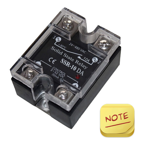
A solid state relay is a four-terminal active device, in which two terminals are input control terminals and the other two ends are output control terminals. It has both an amplifying drive and an isolating effect. And we should know some notes when using SSR relay. In the following, atorelays.com will introduce something about this.
- When selecting a solid state relay for a printed circuit board with a small current specification, since the lead terminals are made of high thermal conductivity materials, the welding should be carried out under the condition that the temperature is less than 250℃ and the time is less than 10S. The load current is generally controlled within 1/2 of the rated value.
- The load capacity of the SSR solid state relay is greatly affected by the ambient temperature and its own temperature rise. During the installation and use process, it should be ensured that it has good heat dissipation conditions. Products with a rated working current above 10A should be equipped with a radiator, and products above 100A should be equipped with a radiator. Equipped with radiator and fan for forced cooling. When installing, pay attention to the good contact between the bottom of the relay and the heat sink, and consider applying an appropriate amount of thermal grease to achieve the best heat dissipation effect. If the relay works at high temperature (40 ℃~80 ℃) for a long time, the user can consider derating according to the maximum output current and ambient temperature curve data provided by the manufacturer to ensure normal operation.
- When the input voltage is too high or the input current exceeds its specified rated parameters during use, it can be considered to connect a voltage divider resistor in series at the input end or connect a shunt resistor in parallel at the input port so that the input signal does not exceed its rated parameter value.
- During installation and use, it should be kept away from electromagnetic interference and radio frequency interference sources to prevent the relay from malfunctioning and out of control.
- When the AC solid state relay is open and the load terminal has voltage, there will be a certain leakage current at the output terminal, which should be paid attention to when using or designing.
- In specific use, the control signal and load power supply should be stable, and the fluctuation should not be greater than 10%, otherwise, measures should be taken to stabilize the voltage.
- When the solid state relay fails to be replaced, the product with the same original model or technical parameters should be selected as far as possible, so as to match the original application circuit and ensure the reliable operation of the system.