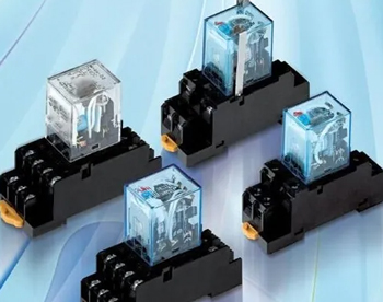
How to Select the Correct Relay?
The essentials of relay selection, relay basic principles, and general knowledge of relay selection, such as modeling by usage environment, relay type determination by various input signals, and type and capacity of relay contacts selection in accordance with load. Relays with good performance are available at ATO relay manufactory for a reasonable price.
Selected based on the environment of use
When referring to environmental conditions, the terms temperature
(maximum and minimum),  humidity (most commonly referring to the maximum
relative humidity at 40 degrees Celsius), low air pressure (use altitude
of 1000 meters or less cannot be considered), vibration, and shock are
typically used interchangeably. Additionally, there are specifications
for insulation, external dimensions, packing, and installation
techniques. Relays can be chosen based on the environmental mechanical
conditions of the entire machine or higher level circumstances, but if
they are subjected to conditions that are greater than those stated in
the product specifications for the environmental mechanical conditions,
there is a danger of damage.
It is advisable to avoid using AC excitation relays near equipment that is susceptible to radio frequency interference or electromagnetic interference. Identify DC relays with coil transient suppression systems. Selecting items with transient suppression circuits is particularly necessary for those who utilize solid-state devices or circuits to generate excitation and are more susceptible to spike signals.
Identify the relay type based on the various input signals
There is no issue with using electric, temperature, time, and light signals as the input signals to choose amongst electromagnetic, temperature, time, and photoelectric relays.
A specific note on choosing voltage and current relays is provided here. If the entire machine supply relay coil has a constant current value, a constant voltage value should be specified for the current relay, and vice versa.
Determining the input parameters
The coil operating voltage (or current) is the input quantity that is most closely associated to the user, whereas the suction voltage (or current) is the parameter used by the relay maker to control, judge, and measure the sensitivity of the relay. It just serves as a working lower limit parameter value for the user. The operating voltage (current) / suction voltage (current) ratio is the control safety factor; if the relay is utilized at the suction value, it is unreliable and unsafe; rising ambient temperature; vibration; and shock conditions will all cause the relay to malfunction.
The coil should be attached as a load to determine the actual voltage while constructing the entire machine rather than using the no-load voltage as the foundation for the relay's operating voltage, particularly when the power supply's internal resistance is high. It is necessary for the transistor to be in the switching state while being used as a switching element to turn on and off the coil. Additionally, the transistor saturation voltage loss needs to be taken into account when the relay's working voltage is less than 6VDC.
In general, the work value for the suction value of 1.5 times, the inaccuracy of the work value is typically 10%. Of course, the higher the work value, the worse it is, as exceeding the rated work value would raise the armature of the impact wear, increase the number of contacts back to jump, and shorten the electrical life.
Choose the relay contact type and capacity based on the load situation
Since contacts account for around 70% of failures, it has been established over a long period of time that relay contacts must be properly chosen and used.
The regulated circuit's actual situation should be taken into account while choosing the contact combination form and the number of contact groups. Due to the contact jump back when connected less frequently and the contact ablation after compensation, dynamic contact groups and change contact groups in dynamic contact pairs have higher load capacities and contact reliability than dynamic brake contact groups and change contact groups in dynamic break contact pairs. The entire line can be properly adjusted by the contact position, as much as possible with dynamic contact.
Determining the parameters is crucial and should be done in accordance with the load capacity size and the kind of load (resistive, inductive, capacitive, lamp load, and motor load). In general, the relay switching load at rated voltage, current larger than 100mA, less than 75% of the rated current is optimum. Contact switching load is regarded tiny and must be more dependable than switching load. 100mA is referred to as the test current and is the domestic and worldwide professional standard for relay manufacturers to evaluate the process conditions and level of content. Current less than 100mA will cause the contact carbon to increase and reliability to decrease. Due to the general relay's lack of low-level switching capabilities, the user must specify and, if necessary, seek assistance from the relay manufacturer when choosing a relay to switch a 50mV, 50A load below the relay order.
The number of times the load is resistive under the rated voltage and current determines the rated load and contact life of the relay. The contact load curve can be chosen in light of the contact load curve when the rated voltage is exceeded.
