How Does Solid State Relay Work?
A relay is an electrical control device that can give a specified input and hold it long enough to cause a predetermined step change in the controlled quantity in the electrical output circuit. Solid state relay is a new contactless switching device composed of solid state electronic components.
It has long service life, fast speed and small interference to the outside world. In this article, atorelays.com will introduce the principle of solid state relay.
Solid state relays can be divided into AC SSR and DC SSR according to applications. Now take AC solid state relay as example to explain SSR working principle. As Figure 1 show, it is a AC SSR working principle diagram and the parts ①~④ form its main body. As a whole, SSR relay only has 2 input terminals (A & B) and 2 output terminals (C & D). It is a four-terminal active device.
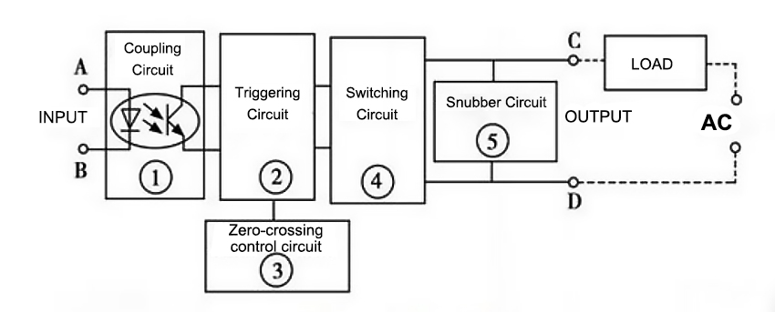
When operating, only place a certain control signal to A&B, able to control on-off state between C and D, and then achieve the switching function. The coupling circuit plays a role to provide a channel between input and output terminals for control signal input from A and B, but cut off the electrical connection between input and output to prevent the output from affecting the input. Components used in the coupling circuits are "optical couplers", which has good action sensitivity, high response speed, high level of input / output insulation (withstand voltage). The load at the input terminal is a light-emitting diode, which makes the single phase solid state relay input very easy to match input signal level. In the use, it can be directly connected with the computer output interface, that is, it is controlled by the logic level of "1" and "0". Trigger circuit function is to generate the desired trigger signal to drive switching circuit work.
However, without special control circuit, the switching circuit will produce RFI (radio frequency interference) and pollute power grid as high harmonics or peaks, so zero-crossing control circuit is set for this purpose. Zero crossing means, SSR is on-state when placing the control signal and AC voltage crossing zero; after switching off control signal, Industrial SSR relay is not off-state until AC current is at the junction the positive half cycle and the negative half cycle (zero potential). This design prevents the interference of higher harmonics and the pollution of the power grid. Snubber circuit is designed to prevent the impact and interference to switching component Triac from the surges and spikes (voltage) from the power supply. Normally RC series snubber circuit or non-linear resistance (MOV) is used. Compared with AC SSR, DC SSR has no zero-crossing control circuit and snubber circuit inside, and large power transistor is usually used for the switching component. In addition, other work principles are the same.